Simple Driveshaft Speed Calculations that Could Prevent a Disaster
Words And Photos: Jeff Smith
We had this crazy notion to race a ’65 Chevelle at the Pony Express. This was an open road race in 1998, and we wanted to enter our car in the 150 mph class where we had to average 150 mph for 90 miles driving on a 2-line primary highway in the Nevada desert. We had performed our top speed versus engine rpm calculations and the numbers looked promising. The plan was to use a Richmond 6-speed manual transmission with a 0.62 overdrive and a 3.55 rear gear. Our top speed simulation program predicted we had enough power to overcome the Chevelle’s hideously poor aerodynamics to run as fast as 170 mph. For the record, the Chevelle was recorded at 168+mph at the Pony Express in 1998.

That spinning driveshaft might not seem like a source of trouble, but when a 20-pound shaft is spinning at 5,000 rpm, it contains a tremendous amount of stored energy. It’s wise to make sure that shaft is happy and safely avoiding its critical speed when spinning at max velocity.
During our planning session, providence stepped in and a friend with high-speed racing experience suggested we speak to a driveshaft specialist about our intentions. Our benefactor mentioned something about driveshaft critical speed — a term with which we were completely unfamiliar. What we discovered was our 38 percent overdrive was going to spin our driveshaft so fast it would easily exceed its critical speed — a very dangerous situation when running at 140-plus mph.
Driveshaft critical speed is the equivalent rpm that matches the shaft’s first order natural frequency. When critical speed is achieved, the driveshaft will begin to whip or bend in the middle. This is crazy dangerous because when this bending occurs, it not only affects balance but also effectively shortens its length and the slip yoke can either be pulled out of the transmission or will fail due to insufficient contact with the transmission output splines.
So, imagine the carnage that occurs when a driveshaft (spinning at 5,500 rpm) fails while the car is running at perhaps 150 mph. All that kinetic energy begins beating on the floor, breaking through the thin sheet metal into the interior, all while the driver is trapped in his seat. It’s not a pretty thing to consider the consequences.
The best way to prevent this disaster is to take a few moments to calculate your driveshaft critical speed if you are considering any top speed runs. In the past 10 years, high-speed measured mile (and now two-mile) runs at airports have become popular. Even long-wheelbase muscle cars are capable of 150 mph passes, so this story isn’t just about a few 200-mph cars.
Securing a more favorable critical speed can be achieved by changing any of several driveshaft variables. We’ve listed these variables in the accompanying chart, but in review, they include the length of the driveshaft, the driveshaft rpm, the tubing diameter, the material, and the true driveline operating angle. While each of these components affect critical speed, it’s the combination of all five that create the final rpm number.
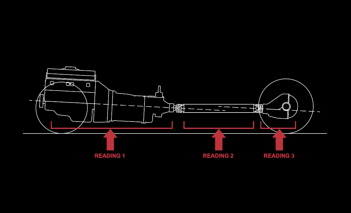
Let’s start with length. As driveshaft length increase, critical speed is lowered, regardless of the shaft’s material. Another way to say that is crucial speed is inversely proportional to driveshaft length. This means that a shorter driveshaft is inherently stronger than a longer unit. Tubing diameter is also a fairly simple concept, as a larger tube will be stronger with an inherently higher critical speed. So, if a change in length is not possible, increasing the tubing diameter will help.
Until a few years ago, driveshaft material selection was limited to steel — either mild steel or 4130 drawn-over-mandrel (DOM) tubing — or aluminum. While these are still viable, we now have a third option with carbon fiber. The advantage to carbon fiber is its incredible strength relative to its weight.
As you can see from the chart supplied by Mark Williams Enterprises, carbon fiber delivers an amazing critical speed advantage for a given length and diameter. A 3.5-inch diameter carbon fiber driveshaft has a 53 percent higher critical speed than a 3.0-inch steel driveshaft. Just as important, several companies now make carbon fiber driveshafts, which means competition should help reduce the price.
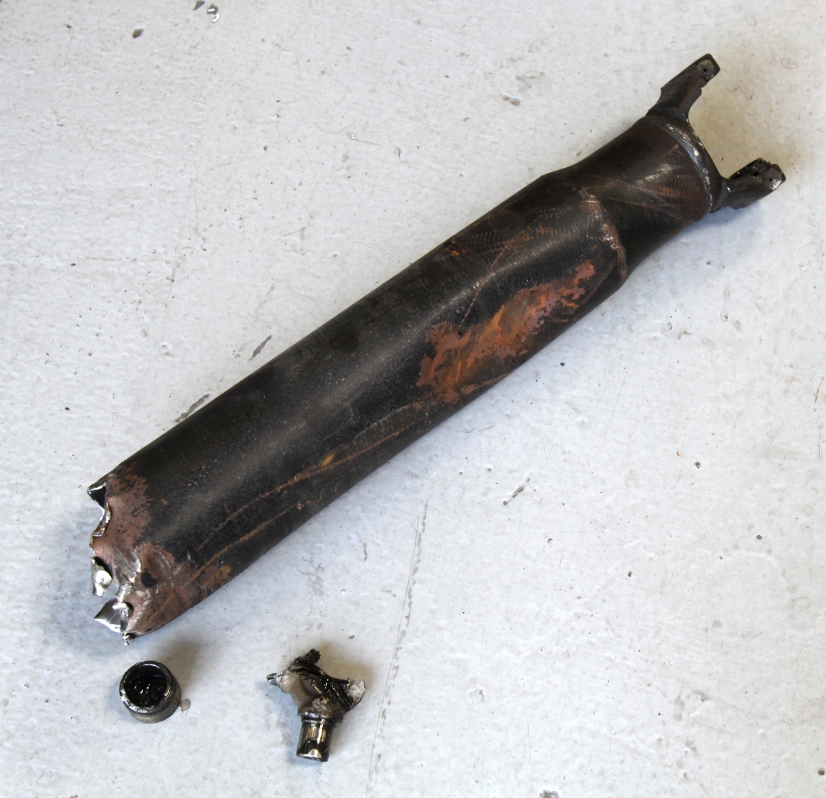
This is what happens when a driveshaft is not happy. Now, imagine this happening underneath the car at 140 mph and it comes up through the floor, hunting for the driver. Not good.
Next is the operating rpm. This may sound simple, but it’s easy to overlook the effect of an overdrive transmission on driveshaft rpm. Let’s take a simple situation where the transmission offers a 0.70 overdrive ratio. Most enthusiasts view the overdrive from the perspective it lowers engine speed, which it does. As an example, as soon as the transmission shifts into overdrive, the engine speed is reduced by 30 percent. But this also means the driveshaft rpm is now 30 percent faster than it was in the 1:1 gear. Stated another way, at 100 mph with a 1:1 high gear, a 3.55:1 rear gear, and 26-inch-tall tires, the engine would spin 6,422 rpm. But add an overdrive ratio of 0.70:1 and the engine speed plummets to 4,495. The driveshaft, however, is still spinning at 6,422 rpm.
The final point is the driveline’s operating angle. This is not just the simplistic angle of the driveshaft. The entire operating angle is a far more complex consideration that considers the operating angles of the u-joints in both the side view and also the top view. This is called the compound operating angle — something that is almost totally ignored, yet can be a significant consideration.
We’ve included a condensed version of a chart that can be found on Mark Williams’ website that lists the critical speed for driveshafts of multiple length, diameter, and material composition. Remember these speeds assume an ideal operating situation with minimum u-joint operating angles. If your operating angles are less than ideal, expect the critical speed to be far lower than what is listed in the Mark Williams chart.
The best way to put all this into perspective is to use a specific example and show how all these factors can be integrated to determine the best driveshaft selection.
Let’s start with some simple calculations to illustrate how the numbers will play out to choose the right driveshaft. To begin, we must be able to calculate driveshaft rpm based on vehicle speed, gear ratio, and drive tire diameter. Here’s the basic formula using a 3.08:1 rear gear and a 26-inch-tall rear tire to calculate engine rpm at 140 mph:
Engine RPM = (MPH x Gear Ratio x 336) / Tire Diameter
Engine RPM = (140 x 3.08 x 336) / 26
Engine RPM = 144,883 / 26
Engine RPM = 5,572
This puts our engine right at peak horsepower at the top speed we desire. This also assumes a 1:1 high gear ratio like with a four-speed. If this was used in our ’65 Chevelle, it also requires a 60-inch long driveshaft. Our chart only goes to 58 inches, so let’s assume we can make a 58-inch driveshaft work. The critical speed for a 3.0-inch steel driveshaft is 5,062 rpm — which clearly won’t work.
The reason this won’t work is that at high speeds, the car is very slowly accelerating as it nears top speed. This means the engine will reside at a little over 5,000 rpm for a long time as it accelerates to top speed. We can’t take the risk of slowly transitioning through the driveshaft’s resonant speed. We will need to find a different driveshaft at the same length that offers at least a 15- to 20-percent safety factor over the critical speed.
This Tremec illustration used in their app indicates the parallel angles necessary to ensure proper u-joint operating angles. Note the engine and transmission angle is tail down with the pinion angle nose up. If the pinion was nose-down, this would produce a conflicting operating angles.
So, what can we do? A 20-percent safety factor would be: 5,572 x 1.20 = 6,686 rpm or higher. On the chart, we can see there are two driveshafts that will give us the rpm we need. One is a 4.0-inch diameter bonded aluminum driveshaft with a critical speed of 6,733. The problem with a 4.0-inch driveshaft in an early Chevelle is that we would have to cut and raise the stock tunnel to clear that large of a driveshaft. The other shaft that would work is a 3.75-inch carbon fiber unit with a critical speed of 7,756 rpm — clearly with more than enough safety factor.
Another solution would be to change the rear gear to a 2.56:1 ratio combined with a 1:1 high gear transmission. This taller gear would put engine and driveshaft speed at 4,631 rpm, which achieves more than a 25-percent safety factor for a 3.5-inch performance steel driveshaft’s critical speed of 5,963 rpm. Note that a 3.0-inch steel driveshaft would still be too close with its 5,062 rpm that does not achieve a 10-percent safety factor.
The only problem with a 2.56:1 rear gear is that acceleration up through the gears will be soft. A popular option is to use a deeper gear for acceleration and then pop the trans into overdrive to reduce total engine rpm. We could use an overdrive unit to slow the engine speed, but remember this increases the driveshaft speed — and can easily push the driveshaft into or past its critical speed. Let’s try a combination to see what that achieves.
The variables are a 3.55:1 rear gear, a 0.62:1 overdrive (Richmond six-speed), a 26-inch-tall tire, and a new top speed goal of 170 mph. That may sound crazy, but it’s close to our original combination with our Chevelle in 1998. For a final drive ratio, it’s necessary to multiply the 6th gear overdrive ratio of 0.62 x 3.55 (rear gear ratio) = 2.20:1 for the final drive ratio.
Engine RPM = (MPH x Gear Ratio x 336) / Tire Diameter
Engine RPM = 170 x 2.20 x 336) / 26
Engine RPM = 4,833
Driveshaft RPM = Engine RPM x Inverse of Overdrive (inverse of 0.62 = 1.38)
Driveshaft RPM = 4,833 x 1.38 = 6,670
As you can see, this doesn’t help because of the excessive driveshaft speed. There were no (affordable) carbon fiber driveshafts available for our Chevelle back in 1998, so we had to revert back to the previous 2.56:1 rear gear combination without overdrive.
Now that we have a handle on critical speed, let’s look at something called half critical speed. First order vibrations occur at shaft speed, but because the u-joints move twice per revolution, a driveshaft spinning at half of the critical speed can create a vibration. This may seem unimportant, but with an overdrive transmission spinning the driveshaft 30 percent faster than engine speed, it is entirely possible. What we want to avoid are those annoying vibrations at normal highway cruise speeds.
Let’s take a look at a common combination of a street gear ratio, a long driveshaft, and an overdrive automatic transmission. The combination in our 383c.i. ’64 El Camino is a 4L60E automatic with a 0.70 overdrive, a lockup converter, a 3.36:1 rear gear ratio, and a cruise speed of 70 mph.
Half Critical Speed MPH Calculation
3.36:1, 4L60E (0.70:1), 26-inch-tall tire, 70 mph
Engine RPM = (MPH x Gear Ratio x 336) / Tire Diameter
Engine RPM = (70 x 2.35 x 336) / 26
Engine RPM = 2,126 at 70 mph
Driveshaft RPM = 2,764 at 70 mph (30 percent faster)
With a driveshaft length of 56 inches, the critical speed of a 3.5-inch diameter, mild steel driveshaft is 6,403 rpm. So half critical speed 6,403 / 2 = 3,201 Driveshaft RPM = 105.4 MPH. To double-check our work, we plug the speed back into this formula:
Engine RPM = (MPH x Gear Ratio x 336) / Tire Diameter
Engine RPM = (105.4 x 2.35 x 336) / 26
Engine RPM = 3,201

A big part of minimizing issues with driveline vibration has to do with ensuring the driveline operating angles are within spec. Tremec offers a free app for smart phones that will measure the operating angles and do the calculations for you. This is our friend Scott Gillman measuring the shaft angle on his Advanced Composites carbon fiber driveshaft — we’re jealous.
So it appears our cruise speed will not be affected by half critical speed issues until we try running the car up to 105 mph. This may create a vibration, but the chances of that happening are slim as long as our operating angles are optimized.
The last words on critical speed should be left to ensuring that the operating angles of the driveline are as accurate as possible. We’ve written a tech story on using the Tremec Driveline Angle Finder App on a smart phone. This app uses the angle function on a smart phone to quickly determine the driveline’s true operating angles. This story can be found on HERE on PowerPerformanceNews.com.
To simplify the driveline operating angle as much as possible, the key with any one-piece driveshaft using a pair of u-joints is to establish the proper operating angles under load. If the engine and transmission are in the typical tail-down orientation, it’s important the rear axle pinion angle be pointed upward at roughly the same angle. So, if the engine was pointed tail down 2 degrees, then the pinion flange on the rear end should be pointed upward at roughly the same angle. An angle difference of up 1 to 3 degrees is acceptable.
This places the two u-joints at minor operating angles so they turn slightly as the driveshaft goes through each revolution. What should be avoided is a conflicting angle where the engine/trans is pointed down and the pinion angle is also pointed down. This creates a conflicting angle that will cause the u-joints to rotate in an ellipse, as opposed to a true circle. Re-orient both u-joint operating angles into a parallel relationship and the u-joints will operate in a true circle and the vibration disappear.
In the early days of racing when race cars struggled to break 100 mph, driveshaft issues were minimal because of the low speeds. But now that street cars have the potential to approach or exceed 200 mph, the physics of a spinning driveshaft become of paramount importance. So, do a few measurements, punch the buttons on your calculator for a few minutes, and see where your combination pencils out. You might be surprised.
Driveshaft Critical Speed Variables
Tube Diameter – larger increases critical speed
Material – Increasing order of critical speed: mild steel, aluminum, carbon fiber
Length – a shorter driveshaft offers a higher critical speed
Angles of Operation – conflicting angles can cause a vibration
Driveshaft RPM – Overdrive increases driveshaft speed compared to engine rpm.
| Driveshaft – Material | 46” | 48” | 50” | 52” | 54” | 56” | 58” |
| 4” Bonded 6061 Aluminum | 10,817 | 9,913 | 9,118 | 8,415 | 7,791 | 7,233 | 6,733 |
| 3.5” 6061 Aluminum | 9,345 | 8,567 | 7,883 | 7,278 | 6,739 | 6,259 | 5,828 |
| 3.75” Carbon Fiber | 12,453 | 11,414 | 10,500 | 9,692 | 8,973 | 8,331 | 7,756 |
| 3.5” Mild Steel 4130 | 9,557 | 8,762 | 8,063 | 7,444 | 6,894 | 6,403 | 5,963 |
| 3.0” Mild Steel ML-600 | 8,129 | 7,450 | 6,854 | 6,326 | 5,856 | 5,856 | 5,062 |
This chart lists the critical speed for five different driveshaft materials and diameters based on length. As length increases, critical speed drops. For example, there is a 37-percent reduction in critical speed for a 3.5-inch mild steel shaft when changing length from 46 to 58 inches. Chart courtesy of Mark Williams Enterprises.
Sources: Advanced Composite Products and Technology, Acpt.com; Axle Exchange, axle-exchange.com; Denny’s Drive Shaft, dennysdriveshaft.com; Inland Empire DriveLine, iedls.com; Strange Engineering, strangeengineering.net; QA1 Precision Products, qa1.net;
Tremec, tremec.com; Mark Williams Enterprises, Markwilliams.com