Checking the bellhousing and related components for concentricity and alignment is the only way to know for sure the clutch will release properly – especially if there are plans for high rpm. If you don’t measure, you won’t know.
Blueprinting the Clutch and Linkage System on early GM Muscle Cars
Words and Photos By Jeff Smith
Anyone who has ever driven a manual transmission knows that secret feel-good moment when you hit that 6,500 rpm, 2-3 shift. It’s like a perfectly timed cymbal crash in rock ‘n roll. The cringe-when-you-do-it side of this exercise is the frustration when that shifter just won’t budge at 6,500 rpm, and the engine bangs off the rev limiter. Everybody within earshot knows you missed that shift. As with all things in life, there are far more ways to screw up a good clutch assembly than there are to getting it right. This means attention to detail can and will improve any system. It just takes some extra effort.
This story will deal with early Chevrolet muscle cars with their somewhat cumbersome mechanical clutch linkage system. We’ll save hydraulic clutch linkage systems for another time. Yes, it’s pretty easy to screw those up too!
Rather than detail a series of problems, we’ll approach this through a series of checks and balances that will give the clutch system in your car every chance to succeed, while minimizing the potential land mines. There is always a solution for every problem — so we’re going to offer a whole pile of solutions. It’s up to you to put ’em in to action.
Let’s start with something we used to take for granted. We used to assume that if we used a factory bellhousing with a factory block, the bellhousing’s center pilot hole would be very close to the crankshaft centerline. We’ve learned you really can’t blindly accept that anymore. There are just too many variables that affect this assumption.
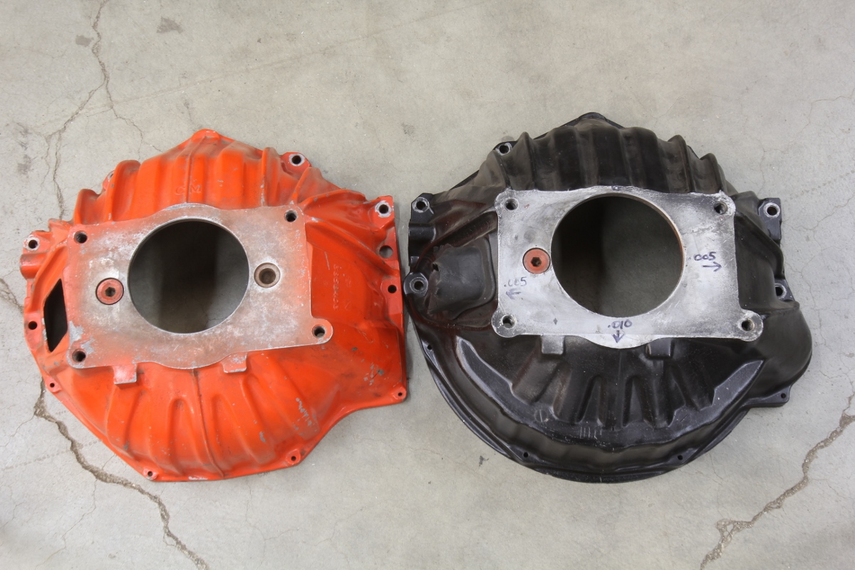
As an example of how easy it is to make a mistake, we learned that part of a clutch release problem with our ’65 El Camino came from the use of the wrong bellhousing. We were using an 11-inch truck style bellhousing that has a distinctive notched shaped to the bottom side. We learned through a friend the pilot hole in this bellhousing is 0.440-inch larger in diameter than typical passenger car bellhousings. This positioned our input shaft way low in relation to the input shaft and caused what is called an energized input shaft. We’ll get to that later. But ultimately, our bellhousing was horribly misaligned by almost 0.040 inch!
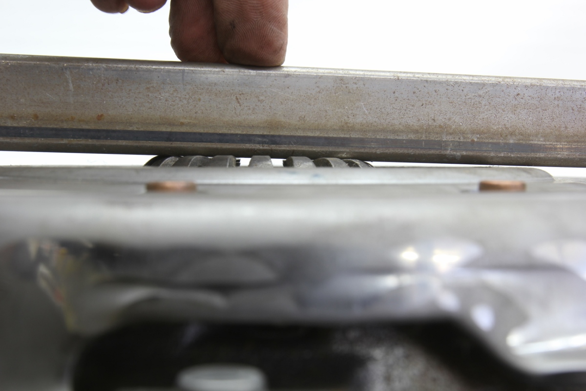
Pressure plate levers low on one side
This photo reveals the pressure plate fingers are not even close to being at a consistent height when bolted down to the flywheel. This will cause horrible clutch chatter. We tried moving the clutch disc around, but this is clearly a defective pressure plate. This is why you should always perform this inspection.
The maximum spec for input shaft runout is a very tight 0.005 inch. This demands explanation because this is referenced against the radius. If we talk total indicator runout (TIR), then 0.005 inch becomes 0.010 inch.
Here’s why this is important. If the transmission’s input shaft is not lined up with the centerline of the crankshaft, bad things begin to happen. A minor discrepancy of 0.10-inch TIR is not cause for concern. But when the number reaches 0.020 inch, this is double the spec, and that’s when the problems begin. As runout increases, this forces the input shaft into a bind where it intersects the crankshaft, because the centerlines of the engine and trans are no longer in line. This places undue pressure and load on the input bushing/bearing.
Where this will most obviously show up is with high rpm shifts. Imagine a car guy who has just installed a new clutch, pressure plate, flywheel, and an expensive overdrive transmission only to discover the shifter balks during high rpm gear changes. The transmission or the clutch will most often be assigned blame. But more often, it’s possible the real culprit is poor bellhousing alignment.
The most often seen issue occurs when attempting to shift into fourth (in a four-speed), or 1:1 in any transmission, since this links the input directly to the output shaft. A misaligned bellhousing makes that high rpm shift difficult, if not impossible. Eliminating the misalignment by dialing in the bellhousing will usually make the gear change very easy. If that sounds simple, it’s only because it is.
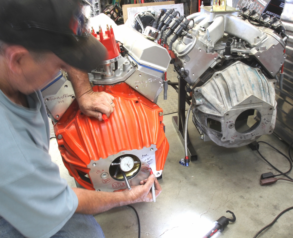
Checking bellhousing runout isn’t difficult, even with the engine in the car, but it will require a dial indicator and a magnetic mount. The hardest part is just setting up the dial indicator. We like to set ours up to read zero at the 12 o’clock position and then slowly rotate the crankshaft. Look for the spot of maximum indicator movement, and mark that position. We use a Sharpie to record both the TIR and the direction of that movement either in or out from the centerline.
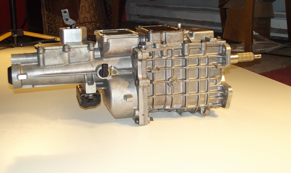
Tremec 5-speed
Newer transmissions like this D&D Performance-modified Tremec TKO-600 or a Magnum 6-speed all use tapered roller bearings to support the input shaft. These bearings do not respond well to a misaligned bellhousing. The symptoms are poor shift quality and missed shifts at higher engine speeds. Older transmissions like a Muncie or Top Loader use a ball bearing on the input that is more tolerant of an out-of-spec bellhousing.
We tested several bellhousings on two different Chevy engines, the first a ’70s 350 small block and then on a 2000-era iron-block LS engine. The first bellhousing we checked was an older 10-inch factory piece. It first checked only 0.005 inch of TIR, putting it well inside the spec. Next, we bolted that same bellhousing to our LS block and were shocked to discover a TIR number of over 0.025 inch! Checking this bellhousing on yet a third engine generated numbers in between. Since the bellhousing couldn’t change, we had to assume the block dowel pin positions on these three engines were different.
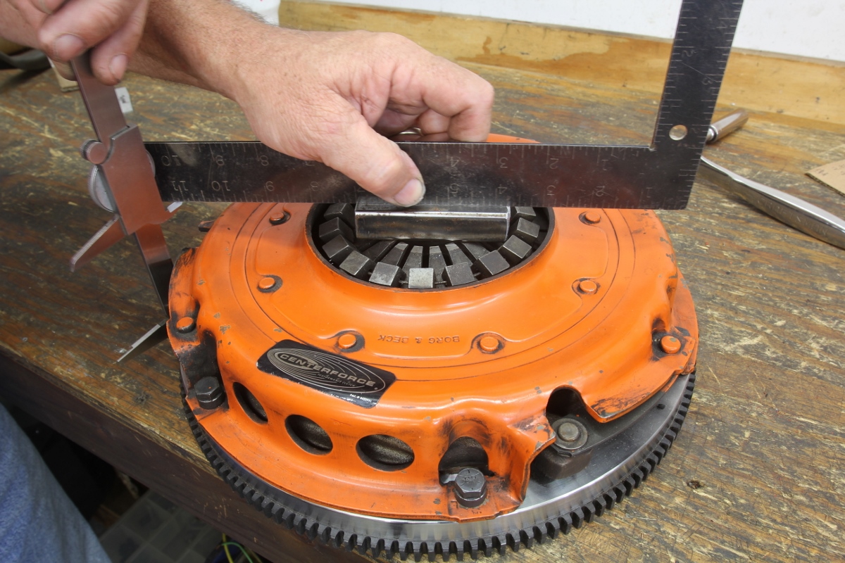
This is how to measure the pressure plate release lever height. The dimension is from the tallest point on the levers to the flywheel friction surface. According to Modern Driveline, this height is between 1.8 and 2.3 inches. This height directly affects the position of the release bearing and the release arm.
This drew us into the obvious conclusion that we were dealing with two separate variables of the dowel pin positions in the block and the location of the dowel pin holes in the bellhousing. With each having the potential to be off center relative to the crankshaft centerline, we could easily fall into either a tolerance stack-up where the numbers became worse, or an offsetting situation where the whole package looked righteous, when in reality each offset the other, despite the fact neither were within spec.
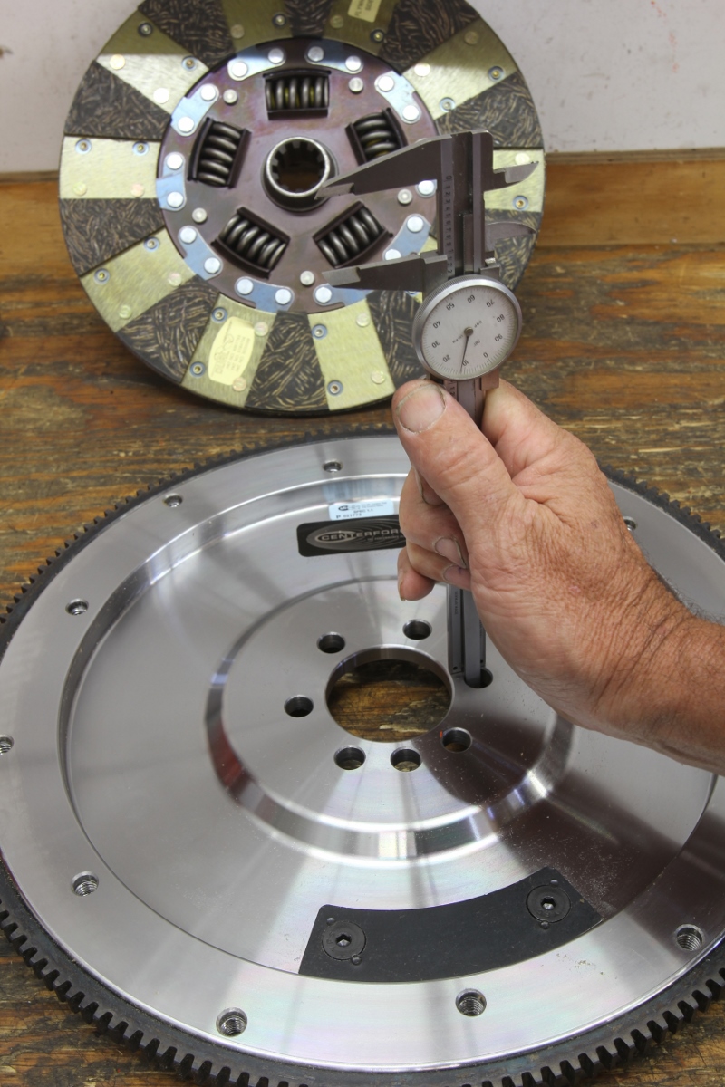
Centerforce recommends measuring the flywheel height as part of the checklist. The spec is 0.960 inch for GM engines using the mechanical clutch linkage. Measure this by inverting the flywheel on a bench and measuring from the crank flange to the bench. If the flywheel is shorter than this spec, this will require lengthening the clutch ball spec the same distance to establish the proper release arm angle.
We spoke with Ross McCombs of QuickTime bellhousings, and he offered to send us a bellhousing checking fixture he used to use. The company now relies on CNC-machining using a CMM or coordinate measurement machine to verify bellhousing accuracy, which relegated that fixture to the shelf. We used this fixture to verify several different bellhousings to at least cut the number of variables in half.
Centerforce illo
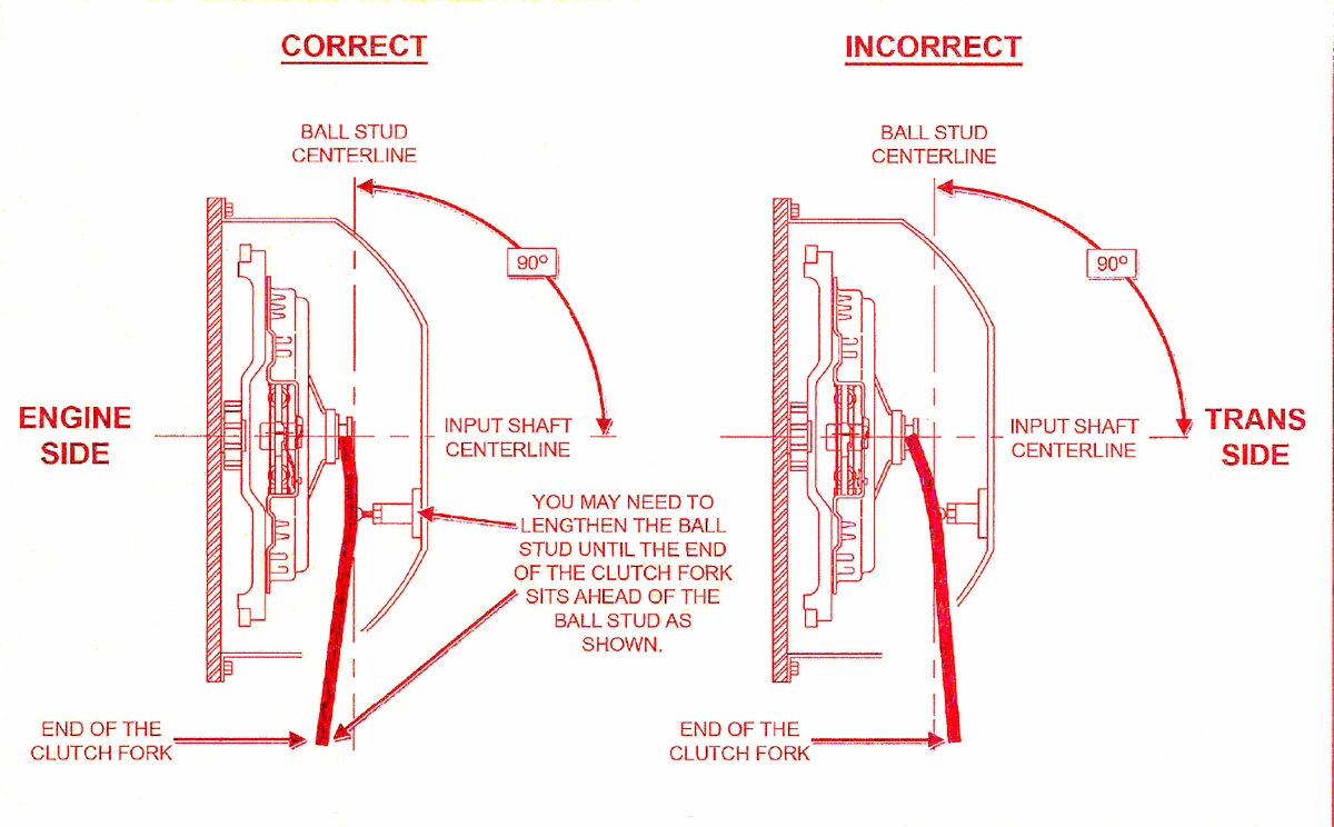
The proper position for the release arm is to be slightly forward of perpendicular to the pressure plate levers with the throw-out bearing touching the levers. This will place the release arm at 90 degrees to the input shaft at half release. This is a Centerforce illustration.
Checking that first bellhousing with the fixture, we learned it exhibited 0.009 inch of TIR. This compared to the 0.005 inch number we measured on our 355c.i. small block, which means the bellhousing and the engine were offsetting the errors. This places the engine’s crank centerline high in relation to the dowels, meaning the dowels are too low.
What this revealed to us is that if you care enough to insist the clutch and transmission work efficiently, you can’t just slap the parts together and let it go at that. You must check everything. We went even further when McCombs suggested we really should start by measuring the parallelism of the block bellhousing mounting face. This is important because if the large pilot hole is not parallel to the crankshaft face, this will cause the pilot hole to essentially become a misshapen cone that will simply never be round.
For a test, we stuck the dial indicator on the crankshaft on our El Camino and discovered the transmission mounting flange on the bellhousing was about 0.008 inch high on the passenger side — roughly the 2 o’clock position. McCombs suggested using a palm-sized whetstone (we found one at Harbor Freight) to check for high spots, such as nicks or blemishes.
The first thing to do is remove all the old paint, rust, grease, and dirt from block-bellhousing face (both ends), and the transmission face. Then use the whetstone to ensure there are no raised edges or burrs. McCombs also recommends using the whetstone to clean the face of the transmission. We did all this and still had a measurement of 0.005 inch. To achieve a zero number, you may have to resort to shims between the block and the bellhousing — ideally with holes in the shims placed over the bellhousing bolts. This will keep them in place.
We discovered one older scatter shield in our collection that was warped by more than 0.15 inch! That one is so bad that we’ve decided it needs to be scrapped.
Next up in the blueprinting process, we measured our old flywheel for vertical runout and came up with 0.004 inch. The spec is 0.002 to 0.003 inch, so the flywheel needs to be dressed. If flywheel runout is worse, it’s worth the time to check the crankshaft flange. We removed our flywheel and cleaned the crank mounting surface with the whetstone.
If, after all of this prep, the bellhousing pilot hole still produces an out-of-spec concentricity number, there is an easy fix. Several companies like Lakewood, Moroso, and RobbMc Performance sell offset dowel pins that can realign an errant bellhousing. The offset dowels come in 0.007-, 0.014-, and 0.021-inch offsets.
As an example, let’s say our bellhousing measured 0.026-inch TIR low at roughly the 7:30 position. This puts the bellhousing centerline 0.013 inch from the crank centerline. The solution would be to use a pair of 0.014 inch offset dowels. This theoretically would put the total offset at 0.028 inch. Taking this to the extreme, even a bellhousing that’s out by as much as 0.048 inch can be saved with a pair of 0.021 inch offset dowels that would bring it back to 0.042 inch. In a perfect worldm the bellhousing would only be misaligned by 0.003 inch on the radius.
With the bellhousing optimized, we can turn our attention to the clutch linkage. Most early Chevrolet manual transmission packages employed a simple z-bar linkage system using a rod from the clutch pedal to the z-bar and another from the z-bar to the clutch release fork. With all stock parts, this system should work well. Most diaphragm style pressure plates require 0.500 inch of release arm travel to fully release the clutch. Given that most passenger car release arms use a 2:1 ratio, this means you will need a minimum of 1 inch of travel where the linkage hits the release arm.
A critical factor that will ensure the clutch releases properly is the position of the release arm. The numbers for the amount of pressure plate release distance vary because of a number of factors such as the clutch disc thickness and the thickness of the marcel spring integrated in between the two friction surfaces on the clutch disc. Mild street clutches tend to have thicker discs than higher performance discs. Because of this variance, it is difficult to put a number of the amount of travel necessary for a disc to release. Our Centerforce clutch only requires 0.27 inch of pressure plate lever travel to create a 0.025-inch air gap of full release.
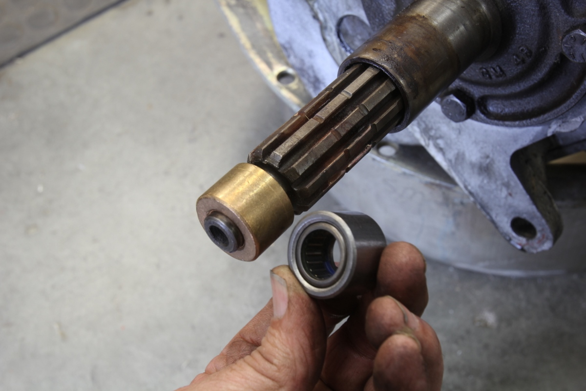
There are proponents of both pilot bushings and bearings. It has happened that pilot bearing can weld itself to the input shaft, making it near impossible to remove the transmission. This makes a case for pilot bushings. Never oil a self-lubricating pilot bushing, as this will clog up the pores in the bushing and cause it to fail.
Other diaphragm pressure plates may require as much as 0.500 inch of lever travel to fully release the clutch. This means the release arm (between the pivot ball and the throw-out bearing) should be perpendicular to the input shaft at half release arm travel — 0.250 inch. This is important because the release arm travels in an arc the pivots around the clutch release ball in the bellhousing.
Will Baty at Centerforce told us a story about a customer who had used a no-name clutch disc with a stock replacement pressure plate and was having problems with inadequate release. The issue: The cheap clutch disc was significantly thicker than a Centerforce. They installed a thinner Centerforce disc, and the problem disappeared because the distance to release travel came back into the proper range.

Summit bellhousing We also tested a Summit Racing aluminum reproduction 11-inch bellhousing on our small-block Chevy and then on QuickTime’s bellhousing test fixture. The numbers came in at 0.034 inch. The other numbers are from different engines we tested. We decided to use this bellhousing and aligned it using a pair of 0.014-inch RobbMc alignment dowels. This brought the total indicated runout (TIR) to 0.006 inch, which was acceptable.
If the release bearing is not in the correct position at half travel, this will increase the travel required at the throw-out bearing. So, if the clutch linkage position is not correct, more linkage travel will be required to release the clutch. Measuring these positions is difficult, especially with the parts installed in the bellhousing.
Included with our new Centerforce clutch and flywheel assembly was a quick example of how to verify the proper release finger height. According to Centerforce, all Buick, Olds, Pontiac, and Chevrolet flywheels for mechanical linkage cars use a common specification for deck height. This is defined as the distance from the crankshaft mounting surface to the friction surface on the flywheel, not the overall flywheel thickness. The deck height spec is 0.960 inch.
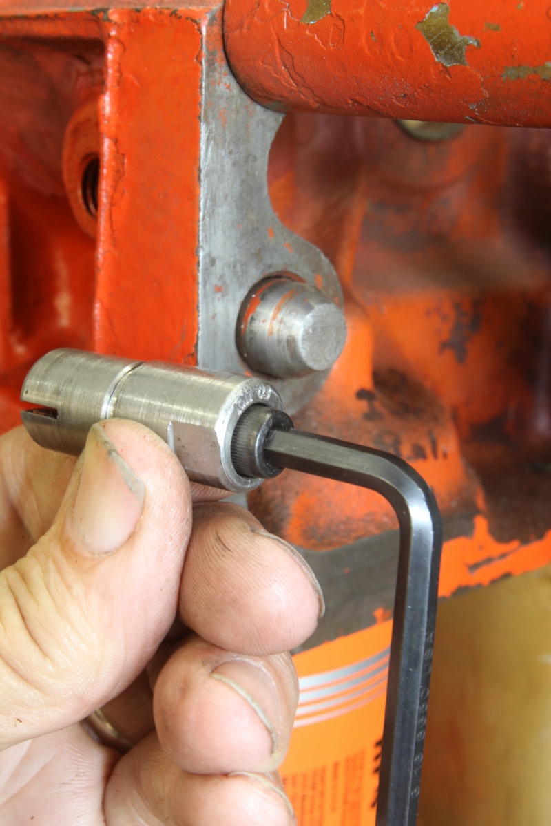
We like the RobbMc alignment dowels because they fit easily into the block and once positioned, are secured with these Allen screws that expand the dowel and lock it into place. Removing it is just as easy. Plus, there’s also 9/16-inch wrench flats that allow easy movement of the dowel in the block.
The whole system is based on the distance from the bellhousing block flange to the top of the clutch arm release ball. This distance should be 4.750. If your flywheel has been machined, perhaps several times, and the deck height distance is less than 0.960, this will require lengthening the ball stud by the difference. For example, if the flywheel thickness measures 0.870 instead of 0.960, this will move the flywheel deck surface (0.960 – 0.870 = 0.090 inch) away from the clutch release ball. This will require an adjustable ball stud that can be lengthened by 0.090 inch to compensate for the thinner flywheel.
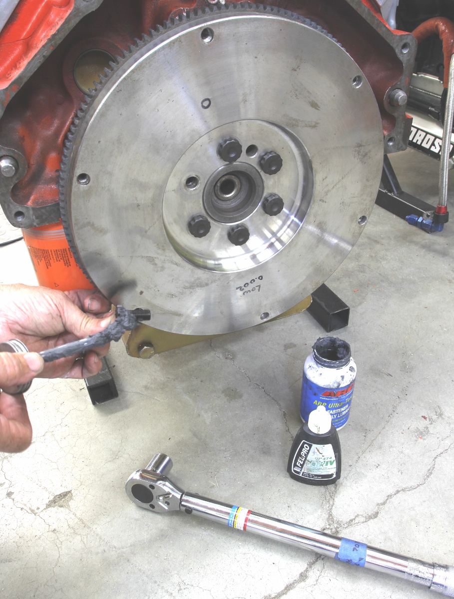
Never install flywheel bolts with lock washers or those hateful star washers. Our Centerforce flywheel came with ARP bolts, and we added a small amount of thread locking compound and then placed ARP’s Ultra-Torque under the head of the bolt. Centerforce lists 80 ft/lbs with oil and 62 ft/lbs with Ultra-Torque — that’s how much better the Ultra-Torque is at reducing friction.
While in the past, it seems like everyone was able to just bolt parts together and make them work, it appears now, that as cars and engines age, specification creep begins to take a toll on parts, and not everything lines up like it once did. Add in that many engines now make twice the power of their ancestors and all those variables have a way of stacking up on the average backyard car builder.
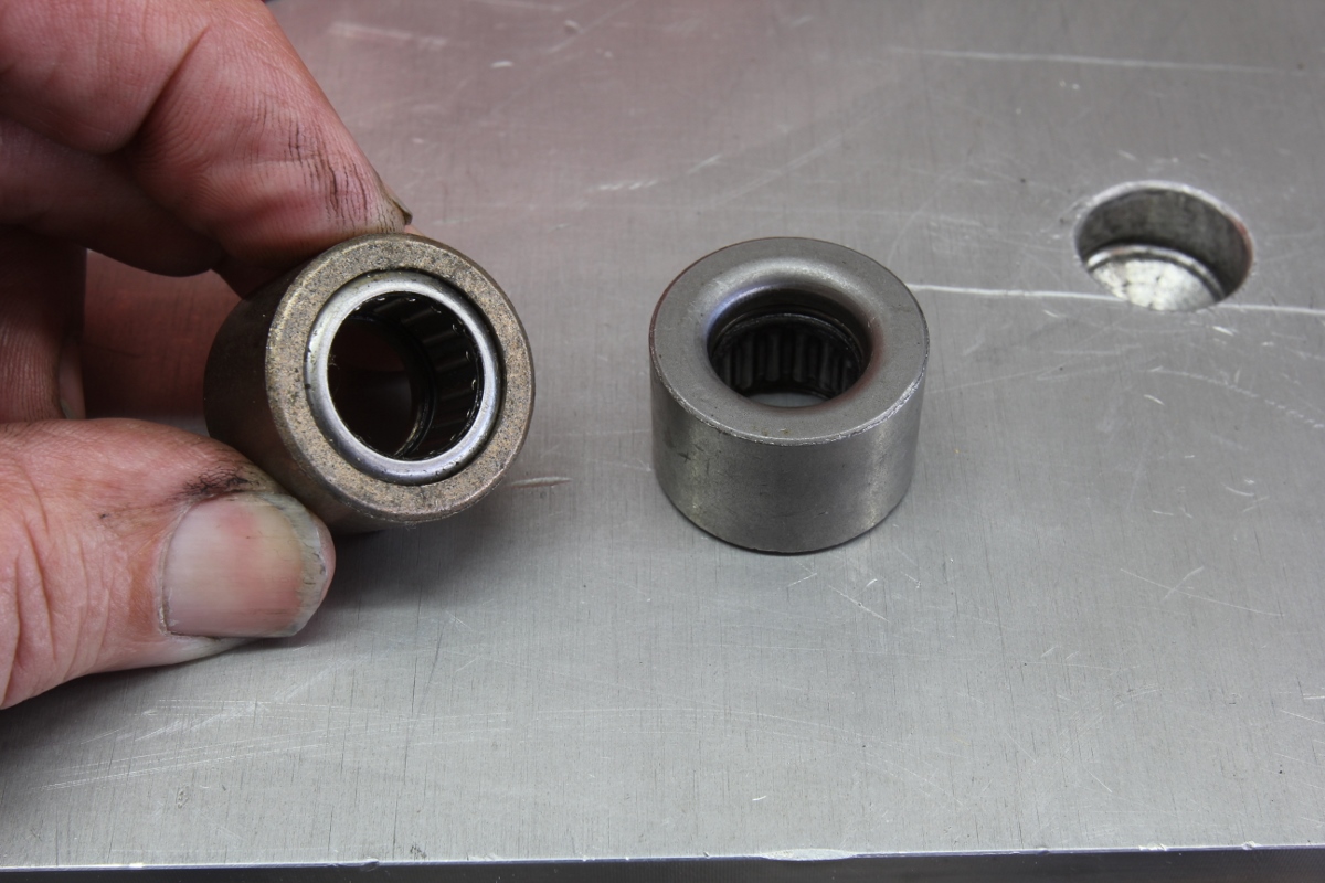
This is another tip from Centerforce. Most pilot bearings come with both an open and closed end. Always install the closed end (right) toward the transmission. This keeps dirt and clutch dust out of the bearing. Centerforce also suggests you add more grease to any new pilot bearing to ensure long life.
So, the bottom line is the only way to know if that brand new clutch assembly is going to work properly is to make the effort to measure the variables and compensate for anything that falls out of spec. It might take a bit longer to finish the project, but the results will be far more gratifying — and it beats the alternative of taking it apart for the fifth time like we did!
Blueprinting Specs
These are Centerforce specs that can be used on any engine. All numbers are in fractions of an inch.
Description Spec
Bellhousing Concentricity 0.005 (radius) 0.010-TIR
Bellhousing flatness – parallelism 0.002
Flywheel flatness 0.002 – 0.003
Flywheel Deck Height (Buick, Olds, Pont, Chevy) 0.960
Torque Specs
Application Torque
(ft/lbs)
Crankshaft bolts (ARP)80 (oil)
60 (Ultra-Torque)
Pressure plate bolts 35-38
Parts List
| Description | PN | Source | Price |
| Centerforce DF clutch assembly | KDF355216 | Summit Racing | $402.38 |
| Centerforce steel flywheel, 1pc seal | 700160 | Summit Racing | $423.06 |
| Summit aluminum 11” bellhousing | 700170 | Summit Racing | $229.97 |
| Quick Time steel SFI bellhousing | 6022 | Summit Racing | $660.95 |
| RobbMc alignment dowel 0.007 | 1011 | RobbMc | $29.00 |
| RobbMc alignment dowel 0.014 | 1012 | RobbMc | $29.00 |
| RobbMc alignment dowel 0.021 | 1013 | RobbMc | $29.00 |
| GM pilot bearing | 14061685 | Summit Racing | $15.97 |
| Dorman pilot bushing | 14650 | Summit Racing | $8.97 |
| Dorman ball stud | 14566 | Summit Racing | $14.97 |
| Dorman clutch alignment shaft | 105325 | Summit Racing | $4.46 |
| Tuff Stuff starter motor | 6510NB | Summit Racing | $119.97 |
Sources: Centerforce, centerforce.com; Holley Performance Products, (QuickTime), holley.com; RobbMc Performance Products, Robbmcperformance.com; Summit Racing, summitracing.com; Tuff Stuff Performance, Tuffstuffperformance.com