Setting proper initial and mechanical advance is the heart of any performance engine. Set the timing wrong and the engine will run poorly. Optimize initial timing with the mechanical /vacuum advance curve and your engine will make more power, run better, and get better fuel mileage than ever before.
Finding Top Dead Center and Setting up Timing Curves
All engines have personalities – some are aggressive, some are demure. Some are rough around the edges and downright skittish below 3,000 rpm. All respond to ignition timing a little bit differently. Timing the arrival of the spark at different engine speeds is critical to pulling every last lb-ft of torque from your engine. Like the question “how high is up?” we need a reference point from which to measure things like time or distance.
With engines, the reference for ignition timing is Top Dead Center (TDC) for piston Number One. TDC refers to the exact moment when the piston achieves its most vertical point of travel in the cylinder. That exact point is then marked on the harmonic balancer, and a reference pointer is located usually on the front timing chain cover. This way, when you hook up your timing light you know where TDC is and when the timing light flashes – you have your ignition timing expressed in degrees Before TDC – BTDC.
All of this is very simple and straightforward and about now you’re thinking, “I know all this. Let’s get to the secret stuff!” The secret we’ve learned over the years is that many enthusiasts forget the basics. We’ve seen dozens of engines with an incorrect TDC mark for the balancer – or no reference mark at all!
How can you intelligently set ignition timing if the TDC mark is incorrect or missing? The answer is you can’t. But we’re going to show you how to find that elusive TDC mark. We’ll also show you how to test your ignition curve without removing the distributor or paying someone to run it up on a distributor machine. You can do it yourself and learn about ignition curves at the same time.
Finding TDC
The first thing to do when setting timing is to ensure that the TDC mark on the balancer and the reference mark actually are indicating an accurate true 0 degrees. It’s a good idea to place the reference mark as close to the balancer as possible. Note that this reference tab is designed for an eight-inch balancer, but the balancer is actually a much smaller 6 ¾ inch unit. The farther the reference mark is away from the balancer – the more potential error can sneak in based on the viewing angle.
Some wags may have already thought of a shortcut to this procedure. “Sure, all I have to do is roll the engine up with the piston at the top and I’m done. I don’t need to go through this whole complicated mess.”
The short response to that approach is if you want your timing marks to all be in error then go right ahead. The problem with just putting the piston at TDC is that if you pay attention, you will notice that the piston will “dwell” or sit at TDC for several degrees of crankshaft rotation before it begins to move downward. The number of degrees of this dwell is determined by the geometry of the engine in terms of stroke, deck height, and rod length.
But all pistons dwell at TDC for a given number of degrees. So we have to stop the piston roughly 20 to 30 degrees on either side of TDC in order to get an accurate reading for TDC.
While lengthy to describe, the procedure is very easy. Let’s say we have a small-block sitting on the engine stand with a harmonic balancer and a pointer whose accuracy you doubt a bit. You could just go with it, but why take the chance? Here’s how you check.
If the engine doesn’t have a pointer, either buy one or fashion one out of aluminum or sheetmetal. Make it robust so that it doesn’t move. If it moves, your efforts are wasted.
Our first step is to clean the harmonic balancer to remove any grease or oil. Next, lay a length of masking tape over the balancer that extends roughly four niches on either side of the TDC mark on the balancer. Place a mark on the tape that indicates where TDC is located on the stock balancer.
Now, fashion a ¼-inch thick rectangular steel or aluminum plate that is large enough to span a 4.5 inch bore and overlap at least two head bolt holes. Drill two or three 7/16- or ½-inch holes in the plate that line up with bolt holes in the block. If the plate will be used for several different engines, it will need multiple mounting holes.
With the cylinder head off the engine, we made up a simple steel plate that bolts to the block and uses a short bolt in the center as a solid piston stop. Bolt the piston stop in place and place a length of masking tape on the balancer and mark TDC. Slowly turn the engine over until it stops. Mark both locations on the balancer.
Next, drill a 3/8-inch hole in the center of the plate and place a bolt through the hole that will protrude into the cylinder roughly ¾-inch. Secure this bolt with a nut that will keep the center bolt tight. If you don’t want to make a piston stop, there are several companies like Powerhouse Products that offer universal piston stops.
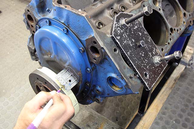
Now that we’ve done our fabrication work, turn the engine over by hand until the piston is roughly two inches below the top of the deck. Bolt the stop plate in place with the center bolt protruding into the cylinder. Make sure the bolts holding the plate to the block are tight. You don’t need to torque them. We use old factory head bolts with stop nuts to secure the stop plate to the block.
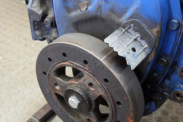
Now carefully rotate the engine clockwise by hand (remove the spark plugs if the other head is still on the block) until the piston gently but firmly contacts the stop. Mark the location on the balancer with a fine marker – make the line thin but easy to see.
Now rotate the engine counterclockwise until the piston again hits the stop, and mark the balancer again. The distance between these two points is the true location of TDC on the balancer. If the new mark does not line up with the original TDC mark on the balancer – think about moving the reference pointer to make the balancer mark accurate. You might want to go with an adjustable pointer to make this process easier. If you adjust the reference pointer, always repeat your test to ensure that TDC is accurate.
If the engine has the cylinder heads in place, we can still perform this same test. The only difference is now we have to use a different piston stop. The easiest ones are simple screw-in stops that take the place of the spark plug in Number One cylinder. Otherwise, the procedure is exactly the same.
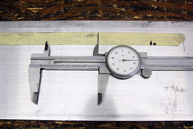
Next, we laid the tape on a piece of aluminum and measured the distance from our TDC mark on the tape to the two stop positions. They were within 0.005 –inch of the same so we’ll call this accurate.
If you want to do this test and don’t have a spark plug style piston stop in your tool box, you can make one. Knock the center electrode out of a spark plug and locate a bolt through the spark plug shell. This is not as easy as it sounds; spark plugs are very well made and removing that porcelain center is not easy. But you can try.
There are certain cylinder heads with spark plug locations that may not allow the screw-in piston stop to work. We’ve experienced this with a small-block Chevy with flat top pistons and AFR heads. In this case, you have to be a bit more creative.
Some guys will try to estimate TDC by using a pressure gauge or a whistle. Don’t waste your time, this doesn’t work. A positive stop is the only procedure. Among the more creative ideas we’ve seen is to use an over-center valve spring compressor tool to open the valve. If you do this, you must create a flat adapter that will only press down on the valve, not the retainer. The over-center tool will hold the valve in a fixed spot – perhaps 0.200 inch off the seat.
Now gently move the crank until the piston contacts the valve and then run through the rest of the procedure. This must be done very carefully. You don’t want to bend the valve! Always rotate the engine over by hand in all these checks.
Checking the Curve
Now that we have located and marked TDC, we can use this location to check initial timing and the advance curve. Many enthusiasts think that they have to remove the distributor and take it to a tuning shop in order to determine the advance curve. That’s not true.
It’s much easier to merely use a timing light on the engine and check the curve with nothing more than a tachometer and a dial-back timing light. An even easier approach is to use a timing tape on the harmonic balancer and a standard timing light. We’ll run through this procedure to show you how easy it is.
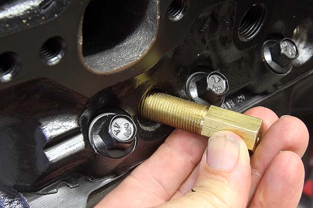
With the heads on the engine, the same procedure works with a spark plug style piston stop like this one. Be careful to always rotate the engine over by hand when using piston stops. Never use a starter motor unless you think replacing broken pistons is fun.
Before we get too deep into this, let’s run through the basics of ignition timing. Initial timing is the amount of timing displayed by your timing light on the balancer with the engine at idle with the vacuum advance line disconnected. Generally, this will be between eight and 15 degrees before top dead center (BTDC).
Mechanical advance is the amount of advance created when engine speed is increased. With a distributor, mechanical advance is created by a combination of eccentric weights and springs on the end of the distributor. Mechanical advance varies between 20 and 30 degrees of advance.
Vacuum advance is created by a vacuum canister added to the side of the distributor and adds timing based on engine load. With low engine load (throttle nearly closed) the manifold vacuum will be high. This pulls on a diaphragm in the canister that advances the timing. When load is high – at or near WOT – there is very little manifold vacuum so the additional advance is not present.
At part throttle the engine will see all three forms of timing added together – initial plus mechanical plus vacuum advance. At WOT, only initial and mechanical will be present.
Let’s start with our established accurate TDC mark. Let’s say the balancer on the engine is only marked with TDC. That’s no problem; MSD makes a very inexpensive timing tape set (PN 8985, $4.95 Summit Racing) with eight different lengths of tapes indicating 10 degrees ATDC to 60 degrees BTDC.
Each of these eight tapes is a different length to match different diameter balancers. The tapes cover balancer diameters ranging from 5.25 to eight inches. Each tape is designed to be used for a specific diameter balancer because as diameter increases, the distance between each degree mark also increases slightly.

MSD sells a very slick sheet of timing tapes with several tape lengths based on the balancer diameter. This sheet of adhesive tapes is very inexpensive, and with one you don’t need a dial-back timing light.
So let’s say you’re really intrigued by this idea of checking your own timing curve, but you don’t want to wait for the UPS guy to deliver a timing tape to you from Summit. You can still do the job by making your own timing tape.
Here’s how it works. Let’s say the balancer on the engine is eight inches in diameter. Circumference is the distance around a circle. The formula is simply Pi x Diameter. You should remember from high school geometry that Pi is 3.1417 inches. Computing 3.1417 x 8 = 25.133 inches.
Now let’s divide 25.133 by 180. Why? Because we’re going to make marks on a piece of masking tape every 2 degrees rather than every 1 degree. Dividing 25.133 by 180 equals 0.139 inch. Now we’ll make a TDC mark on a six-inch length of masking tape laid on a length of sheet aluminum to make it easier to mark.
Let’s start by using a dial caliper to mark 10 degrees. Since our 0.139 is every two degrees, multiply that by five and we get 0.698 inches. Set that length on the dial caliper and mark the tape every 20 degrees for 10 – 20 – 30 – 40 – and 50 degrees.
Since we want to use our tape to determine our curve at different rpm points, the tape will need to be accurately laid out every two degrees from 10 through perhaps 40 degrees. Once that is set, now all you have to do is clean the balancer and lay the tape on it.
Now we can actually get into the procedure for checking our advance curve. The best way to do this is to have a friend help you. Hook up an accurate tachometer to the engine and attach the timing light to Number One spark plug wire. Also make sure to remove and plug the vacuum line going to the vacuum advance canister on the distributor. This is important because we want to separate the vacuum advance from the mechanical.
Now start the engine and record the initial timing at idle. Let’s say the number is 10 degrees at 850 rpm. Next, have your friend run the engine up to 1,500 rpm and record the amount of advance. Let’s say this is 14 degrees. Next, record the timing numbers every 500 rpm up to wherever the timing stops advancing. This may require revving the engine up to 4,000 rpm or perhaps higher. We’ve created a curve below as an example:
Mechanical Advance Curve
| RPM | Degrees Advance(Mechanical) |
| 850 | 10 |
| 1,500 | 14 |
| 2,000 | 18 |
| 2,500 | 22 |
| 3,000 | 26 |
| 3,500 | 30 |
| 4,000 | 32 |
| 4,500 | 32 |
This is a linear curve advancing four degrees every 500 rpm. As a performance engine curve, this is somewhat slow. Conventional wisdom places a typical performance curve with all the timing in by 2,500 to 2,800 rpm. Most street engines respond well to having more timing at lower engine speeds, especially when using even a mild performance camshaft.
Before we jump into changing the mechanical curve, let’s finish the total curve by now re-connecting the vacuum advance line between the carburetor and the advance canister. Run through the exact same procedure as before.
You will notice that vacuum advance will hit its maximum advance pretty quickly. It actually will have a curve based on vacuum levels that will not show up on this kind of test. If you really want to do an in-depth test to know the amount of advance at lower manifold vacuum levels, you can use a portable hand vacuum pump like a Mighty Vac to create vacuum levels from two to 10 inches in two inches of Hg increments and plot each of these levels.
This will give you the most accurate idea of advance at different throttle openings, but it gets a little complicated. This basically creates a three-dimensional plot that will look just like the ones plotted for EFI engines. We’ve included a cool FAST XFI graph of what this three-dimensional graph looks like, but you don’t have to go to these lengths to get an idea of what the vacuum advance will do.
The chart below indicates the total amount of timing at each rpm with the vacuum advance added to the mechanical. The numbers in parenthesis are just the vacuum advance – which was determined by subtracting the mechanical advance from the total advance. Again, this is only the maximum; with lower manifold vacuum, the vacuum advance figures would also be lower.
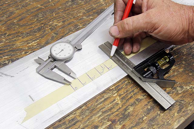
If you are in a hurry, you can build your own timing tape with a dial caliper and length of masking tape. Make sure than when you stick the tape on the balancer that zero on the tape is dead even with the TDC mark on the balancer.
Mechanical + Vacuum Advance Curves
| RPM | Degrees Advance(Mechanical) | DegreesVacuum + Mechanical |
| 850 | 10 | 10 (0) |
| 1,500 | 14 | 26 (+12) |
| 2,000 | 18 | 32 (+14) |
| 2,500 | 22 | 36 (+14) |
| 3,000 | 26 | 40 (+14) |
| 3,500 | 30 | 44 (+14) |
| 4,000 | 32 | 46 (+14) |
| 4,500 | 32 | 46 (+14) |
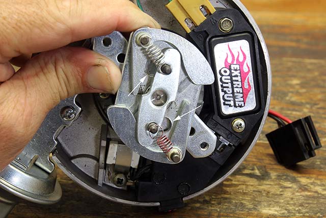
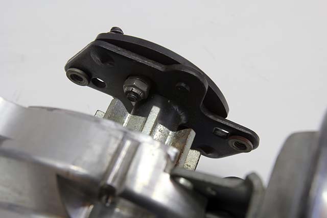
Nearly all distributors use a pin in a slot to determine the amount of mechanical advance allowed. The length of the slot as well as the size of the pin and its bushing limit the amount of advance. This is an HEI distributor, and the arrows indicate the two slots with pins that protrude through the plate. You can lengthen this slot to increase mechanical advance or braze it up to reduce its travel distance to reduce total advance.
As you can see, with just the mechanical advance the distributor is only adding a maximum of 22 degrees (32 – initial 10 = 22 degrees mechanical advance). If we decide that the engine needs 36 degrees of total timing to make best power then we need to add four degrees more timing. In this situation, that’s easy because all we have to do is add four more degrees of initial timing and we’re there.
But what if we need more total advance but the engine tends to run into light detonation when you crowd the throttle at peak torque so that you can’t just add it to the initial? There’s a way to do this too.
We’ll use an MSD distributor to illustrate this point since these distributors give you an easy way to alter both the speed of the curve (how quickly or slowly it advances) and the total amount. All mechanical advance MSD distributors use a pin in a slot to control the maximum mechanical advance. MSD places different diameter bushings over this pin to limit the amount of advance. These various bushings are supplied with any new MSD distributor.
There are four different bushings: black (18 degrees), blue (21 degrees), silver (25 degrees), and red (28 degrees). The number in parenthesis is the amount of mechanical advance each bushing will allow. So if we have a total of 22 in our distributor and need 26 – the closest bushing will be silver. With 25 degrees and 11 degrees initial, we will have 36 degrees of total advance.
MSD distributors use a single pin and slot but also employ a bushing over the pin that can be easily changed. Remove the c-clip and you can replace the bushing with one of three other diameter bushings that regulate total mechanical advance.
What if all you have is a stock distributor and you need to add or subtract mechanical advance? That takes a bit more work, but it can also be done. Let’s say we have an HEI distributor and we need to add more mechanical advance. You will have to remove the distributor from the engine and then disassemble it to remove the main shaft.
Just like the MSD distributor, there is the same pin and slot arrangement – except there are two pins and two slots. To increase the mechanical advance you will need to elongate the slots. This won’t be easy as this is hardened steel, but it can be done. The amount to elongate will have to done through trial and error. Sorry.
Now we can talk about the shape of the curve. Again, with an MSD distributor it’s easy because MSD has already worked out the combinations of springs that will produce the desired curve. For a typical street engine with 9.5:1 compression and a performance cam, running a fairly quick advance curve is a good way to build low- and mid-range torque. The combination of the light silver and light blue springs will produce a quick curve that should be all in by 3,000 rpm.
Since the springs are easy to mix and match just by removing the distributor cap and rotor, you can experiment with different curves to see how your engine reacts. Once you find a curve that fits your application, you really won’t see a need to change it unless you make a major change to the engine.
Conclusion
There are more in-depth tuning details that we can get into in a follow-up story if there is enough interest where details like compression ratio, inlet air temperature, air-fuel ratio, mixture distribution in the intake manifold and a whole bunch of other details all come into play. But for most cars, just setting a performance oriented initial timing with a strong advance curve will make a big difference in both part-throttle and WOT acceleration. And the best news is that you can do nearly all of this with just hand tools, a modicum of effort and some enlightened tuning decisions. It’s really that easy. So get started!
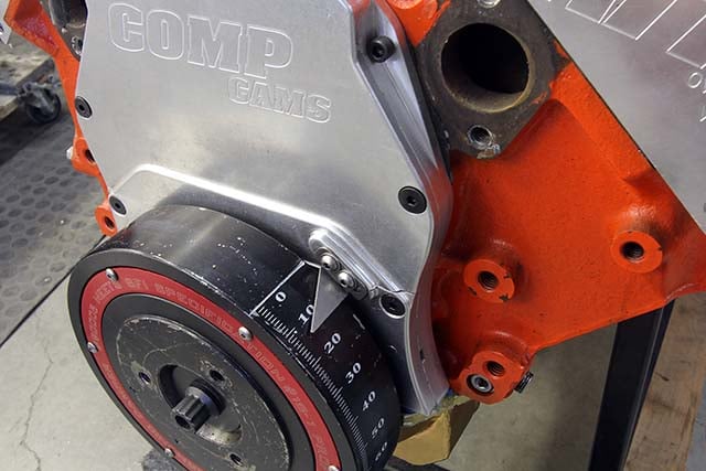
Engines with marked balancers are easy to check as you don’t need a timing tape. A standard timing light will work. Note here on this big-block that we are using the straight edge of the reference plate to indicate zero.
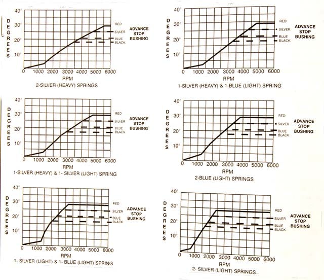
The curves shown here are on MSD’s website if they are too small in this photo to be useful. The curves indicate the shape of the advance curves by using various combinations of springs with an MSD distributor. These are only accurate when used with an MSD distributor.
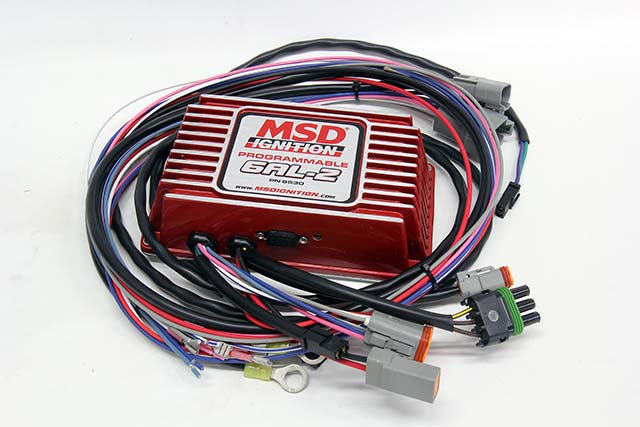
If all this seems like way to much work, you can go to a fully electronic ignition curve system employing an MSD programmable 6AL-2 (PN 6530) that creates an electronic ignition curve. This box requires a locked out distributor, which is easy to do on any MSD distributor. Any advance curve is easy to create using MSD’s Pro-Data + software and a laptop. We’ve used this and it’s much easier than messing with weights, springs, and vacuum cans!
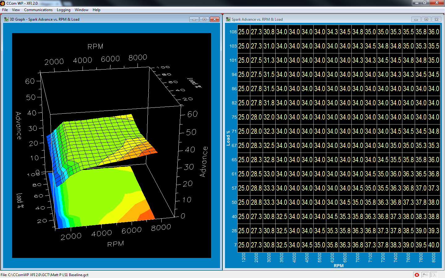
This is a three dimensional graph from a FAST XFI program showing how timing is determined by a combination of rpm and load.