Tuning a carbureted street engine with a big camshaft isn’t all that difficult. The key is to separate the ignition from the fuel system, tune them separately and then perform the final tuning to optimize the combination.
How to Adjust Your Carb and Ignition to Improve Drivability without Sacrificing Power from that Monster Camshaft
Words And Photo: Jeff Smith
Carburetor companies hate big camshafts. If you ask, they’ll tell you they get more tech questions about how to make a street engine work with a big cam than almost any other issue. The other big issue – and in America it’s all about being big – is that street camshafts are often chosen as much for their lumpy idle quality as for their power potential. So now that we’ve established that it’s not uncommon to find lots of street engines with a very large carburetor bolted to an engine with a cam with too much duration.
Rather than preach conservatism to our assembled choir of admitted street radicals, the next best thing is to make this big cam selection run as cleanly as possible. The most common issues associated with a long-duration cam on the street are a very rich idle mixture, mild to outright annoying hesitation under light acceleration, very rich part throttle operation, an extreme bog under hard acceleration, extremely poor fuel mileage, fouled spark plugs and in general very poor throttle response. If any of these descriptions fit your street car, then we will suggest some simple fixes that should help your car run better. This is actually a fairly complex subject so we won’t be able to get into all the solutions. For this story, we’ll hit a couple of simple and easy fixes. If there is enough interest in this subject, we can return with more recommendations that will also help. But for now, we’ll stick with the quick and easy fixes. And just to make it interesting, we’ll start not with the carburetor but instead with the ignition.
Timing the Spark
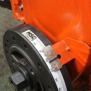
Starting with the ignition, the first priority with a big camshaft is to add initial timing. A good starting point is 15 degrees initial timing. If your engine does not have a degreed balancer, use an MSD timing tape (PN 8985) that will allow you to read 40-plus degree timing figures with a traditional timing light.
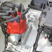
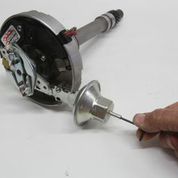
All factory distributors come with vacuum advance as do many performance distributors like this MSD. While some engine tuners will scoff at vacuum advance distributors, they are extremely useful for street engines with big cams.
One of the biggest problems with big camshafts is when the cam is added to an engine with insufficient compression. In most cam catalogs, the larger camshaft descriptions include a compression ratio recommendation. For example, COMP’s Xtreme Energy hydraulic flat tappet XE294H cam with 250/256 degrees of duration at 0.050 and 0.588/0.593 inch lift and a 110-degrees lobe separation angle (LSA), recommends no less than 10.5:1 compression when using this cam. This recommendation is often ignored when selecting this cam but it actually is there for a very good reason. As intake duration increases, the intake closing point occurs much later. If you think about it, the engine cannot begin to compress the intake charge until the intake valve is closed. So the engine’s effective compression will be much lower than its static compression ratio because the intake valve closes later. This results in reduced cylinder pressure—especially at low engine speeds. That’s why after a big cam is installed in your engine, it seems like the engine feels sluggish at lower engine speeds. It feels sluggish because the engine has lost a significant amount of cylinder pressure. Proof of this is to perform a cranking compression test before and after the cam swap. What you will find is that the big new cam has reduced the cranking pressure by perhaps 10 psi. The engine has not lost ring seal – the later closing intake valve prevents the engine from creating cylinder pressure until the intake valve closes.
The best way to maintain a cranking compression of around 180 to 190 psi with a long-duration cam is to increase the static compression ratio. But that requires different pistons, or a smaller chamber cylinder head. Unfortunately, both of these approaches are expensive and demand quite a bit of effort. But there is a way to gain back some of that lost power through tuning.
Most stock engines use relatively conservative initial timing numbers. Even the late ’60s performance engines only spec’d single digit initial timing numbers. The initial timing spec for a 1969 SS 396 Chevelle engine equipped with a solid lifter camshaft and a 750 cfm Holley carburetor was a paltry 4 degrees BTDC. But this engine also had 11:1 compression and a cranking compression of 160 psi. A more modern street performance engine may run something closer to 10 to 12 degrees of initial timing. The problem today is that with an engine with a big camshaft and low static compression of around 8.5:1, it needs more initial timing.
Let’s assume for example, that we have a 454 Big Block Chevy that came out of a truck that’s now in between the fenderwells of your street Chevelle and the engine now has our previously mentioned XE294H camshaft, but the engine only has an 8.5:1 static compression ratio. In this case, we should bump the initial timing up to something closer to 15 to 18 degrees of initial timing. Starting the spark sooner in the combustion process will help the engine’s low-speed throttle response. However, this will probably put the total timing (initial plus mechanical advance) far too advanced once all the mechanical advance has been added in. Let’s say that the distributor’s mechanical advance adds 26 degrees of total advance. Adding 15 + 26 = 41 degrees of total ignition advance. Most street engines today run best with 34 to 38 degrees of total timing. In this case, the easiest thing is to limit the initial timing to 10 degrees – making the total 10 + 26 = 36 degrees.
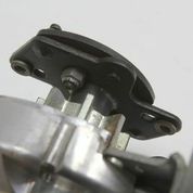
All centrifugal advance MSD distributors place a bushing over a pin in the advance plate that allows quick and easy changes to the mechanical advance total. All MSD distributors come out of the box with the black limiter bushing. This is helpful in allowing more initial timing. Less mechanical advance in the distributor allows more initial timing for a given total.
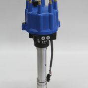
Crane offers an interesting optical trigger electronic distributor that you might consider that allows the tuner to select the amount and rate of advance with the twist of a couple rotary dials. Minimum mechanical advance is 20 degrees. This distributor will also add “vacuum advance” timing when hooked to a manifold vacuum source with three choices of 12, 16 and 20 degrees. This distributor requires a CD amplifier like the Crane HI-6 or the new FAST E6 CD box.
Unfortunately, this doesn’t help our low-speed drivability problem so we have to go inside the distributor to limit the total mechanical advance. If you are lucky enough to be using an MSD distributor, then this step will be easy. MSD includes several bushings that can be used to limit the mechanical advance. In this case, we’d like to limit the mechanical advance to 21 degrees total. This will allow us to set the initial timing at 15 degrees for a total of 36 degrees. MSD supplies four different bushings: black – 18 deg.; blue – 21 deg.; silver 25 deg.; and red – 28 deg. These numbers indicate the total amount of advance available from the distributor. Let’s take the blue with 21 degrees, which gives us 15 degrees for initial timing. Assuming our advance curve starts at around 1,800 RPM, we now have roughly five more degrees of initial timing at lower engine speeds. If we also change the springs in the distributor so the curve is all in by 2,400 RPM, then this should also improve throttle response.
If the engine still seems sluggish or slow to accept throttle, we can try one more major change. This requires a distributor with vacuum advance. In most factory applications, the vacuum canister is connected to the ported vacuum outlet on the carburetor. This eliminates vacuum advance at idle. But with a really big cam and low static compression, you may need as much as 20 degrees of initial timing, which is difficult to achieve because you have to limit the mechanical advance to only 16 degrees. Instead, try hooking the vacuum advance hose to straight manifold vacuum. If your engine idles at only about 8 to 10 inches of manifold vacuum, this may only add 5 or perhaps 10 degrees of timing at idle, but that may improve throttle response enough to warrant the change. It’s a simple trick but very few tuners think to use it. Now you know more than they do.
At this point we must also point out the obvious that adding over 10 degrees of ignition timing to a street engine may create issues with low-speed detonation. Add a few degrees of timing at a time and then perform a road test. Finalize the initial/mechanical/vacuum advance curve with the usual caution to stay away from detonation. If the engine rattles, pull the timing back or slow the rate of advance to help eliminate detonation. Also remember that a cold inlet air system is very helpful in reducing an engine’s tendency to rattle—especially at part throttle. Even a 10-to-15 degree reduction in inlet air temperature is significant.
Carburetor Changes
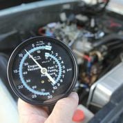
A simple vacuum gauge hooked to manifold vacuum can be a very useful tool for setting both idle mixture and initial timing. With a long-duration cam, if vacuum improves with 4 degrees additional timing, add more until the vacuum stabilizes. This will help you choose an initial timing figure.
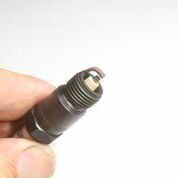
Of course, our tuning suggestions are based on the assumption that you are using the correct spark plug and high-quality plug wires. Drag racers often employ colder plugs, but for street use the stock heat range or one step colder is a better choice. Extended nose plugs like this Autolite are also preferred, placing the spark closer to the center of the chamber.
Now we can move to the fuel side. Generally, engines with large camshafts are also fitted with large cfm carburetors. We’ll assume for this discussion that a large carburetor to be anything 850 cfm and larger. Holley carburetors are the most popular so our discussion will deal with these carburetors but the basics of what we will be discussing can and does apply to other carburetors. Long duration camshafts generally also incorporate greater amounts of valve overlap. This combination of long duration with a late closing intake and a greater amount of valve overlap seriously reduces idle manifold vacuum. It’s not unusual for a big cam small-block or big-block engine to experience less than 6 inches of manifold vacuum. When an engine is idling with the throttle blades closed, the manifold vacuum is what creates the signal that moves fuel. As this signal is reduced (lower manifold vacuum), carburetor builders compensate by increasing the size of the idle feed restrictor. This idle feed restrictor is essentially the main jet for the idle circuit. The idle air bleeds in the carburetor also affect the fuel flow, but the component that has the greatest effect on idle fuel flow is the idle feed restrictor.
Since every performance engine is different, it’s inherently difficult to build a universal carburetor that is tuned correctly for each application. So the carburetor companies must design their carburetors on the rich side to ensure they run properly right out of the box. This means that we can almost assume with some certainty that in most big-cam engines with a large carburetor the idle circuit will be overly rich. The best way to deal with this situation is to restrict the total amount of idle circuit fuel flow. You can experiment with the idle air bleed, but our experience shows that these changes are more for very fine tuning effects. With these big carburetors, we need to make a major change in the fuel flow.
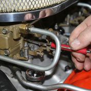
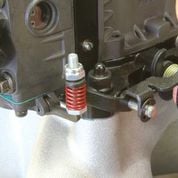
Did you know that many aftermarket vacuum advance canisters are adjustable? The ones with a hexagon shape are adjustable for total and rate. Using a small Allen wrench, there are 10 -12 turns of adjustment to limit the amount of vacuum advance. This is an Accel unit PN 31038 for an HEI.
Always balance the idle mixture screws with the same number of turns. Set idle mixture as lean as possible as long as the engine does not stumble at part throttle.
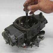
All modular (4150, 4160 and 4500 series) Holley carburetors place the idle feed restrictor in the main metering block. If your Holley has four idle mixture screws, then there will be four separate idle feed restrictors. Otherwise we will be dealing with just two idle mixture circuits in the primary metering block. Holley began building HP-style carburetors several years ago and these carburetors are fitted with screw-in replaceable bleeds in all the critical circuits. Older Holleys use a press-in bleed or restrictor. We will deal with the more common press-in bleed since changing screw-in bleeds easy, assuming you know your way around a screwdriver.
For press-in bleeds, the tuner is faced with two choices. We can mix up some epoxy, fill in the restrictor and then drill it out or we can use a simple length of small diameter wire to act as our tuning device. We would suggest going the wire route in the beginning until you have some experience working with the idle feed restrictor. Then you might consider making permanent changes.
Let’s first get into a specific application with a Big Block Chevy fitted with a big Holley 950 HP Ultra carburetor. We can get a sense of where the current idle feed restrictor is (too big or too small) by evaluating the idle mixture’s screw settings. Holley prefers to have the idle mixture screws start at roughly 1 ½ turns out from fully seated. The farther the idle mixture screws are turned out from fully seated, the more fuel is delivered. So let’s say that the 950 carb on our Rat has the idle mixture screws set for best idle vacuum but the screws are turned out barely ½ of a turn. This tells us that the idle feed restrictor is so big that we have to restrict that flow with very few turns on the idle mixture screws. Conversely, if the screws were turned out three full turns, it would tell us the idle feed restrictor is a bit too small. But the most common situation is the restrictor is too large.
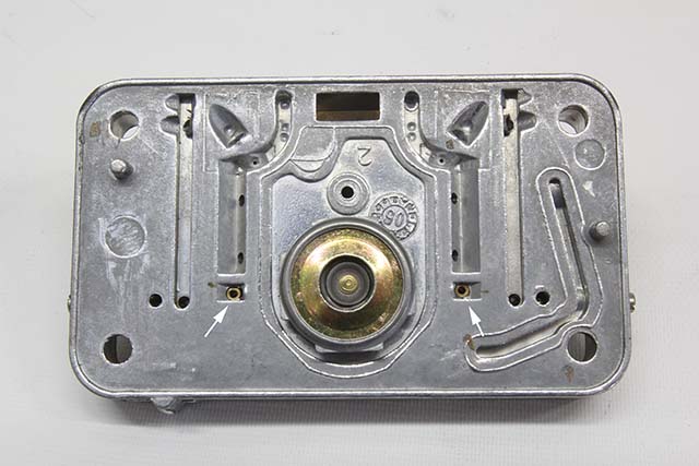
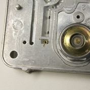
Holley and aftermarket performance metering blocks place the idle feed restrictor in two different locations. The more common position is indicated by the arrows. Note that the restriction is not the large size you can see but a much smaller 0.030- to 0.042-inch hole at the bottom of the cup-shaped bushing.
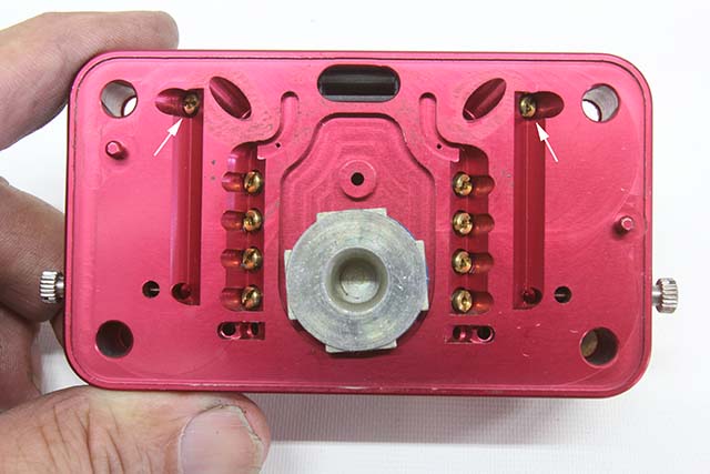
The second and less common idle feed position on a Holley metering block is the upper locations noted by the screw-in bleeds (arrows). Screw-in bleeds are obviously much easier to change but require purchasing a collection of different size bleeds.
We next measured the idle feed restrictor in our 950 HP at 0.042-inch for a baseline. Typically, a 750 cfm Holley mechanical secondary carburetor would have a much smaller, 0.035-inch idle feed restrictor. This is closer to what we would consider the correct size idle feed size for our 468c.i. Rat. So now we have an idea of how much we need to reduce the fuel flow. The important point here is that we are dealing with the area of a hole – not the diameter. So the first thing we have to do is determine the area of both what we have and where we want to end up. Area of a circle is determined by using the formula:
Area = Pi (3.1417) x radius x radius
Radius is the diameter of the circle divided by 2 which for our big 950 carburetor would be:
R= 0.042 / 2 = 0.021
The area for our 950 carb idle feed restrictor is: A = 3.1417 x 0.021 x 0.021 = 0.00138549 square inch
Now let’s compute the area for a 0.035 restrictor.
A = 3.1417 x 0.0175 x 0.0175 = 0.00096214 square inch
Simple subtraction gives us a difference in area of 0.00042335.
We generally use a 0.015 diameter wire as a starting point, but the area for that wire is only 0.00176, which is less than half of the area difference we were shooting for. We had to increase the wire diameter to a 0.020-inch wire which is still smaller than the difference but should get us close to establishing a leaner idle circuit. We’ve covered the technique in the photos and captions so we won’t duplicate that information here, but it’s important when working with these restrictors that you make sure the wire feeds all the way into the tiny hole in the restrictor, which is in the bottom of the brass cup.
Once the wire restrictors are in place, you will then need to readjust the idle mixture screws. Start by placing them roughly one full turn out from fully seated and then adjust all four screws the same amount to balance the fuel flow. With the engine warm, set the idle mixture to its best idle speed (or highest manifold vacuum) and then take the car for a test drive. If the engine hesitates with mild throttle just off idle, then you may have to readjust the idle mixture slightly richer to eliminate that hesitation.
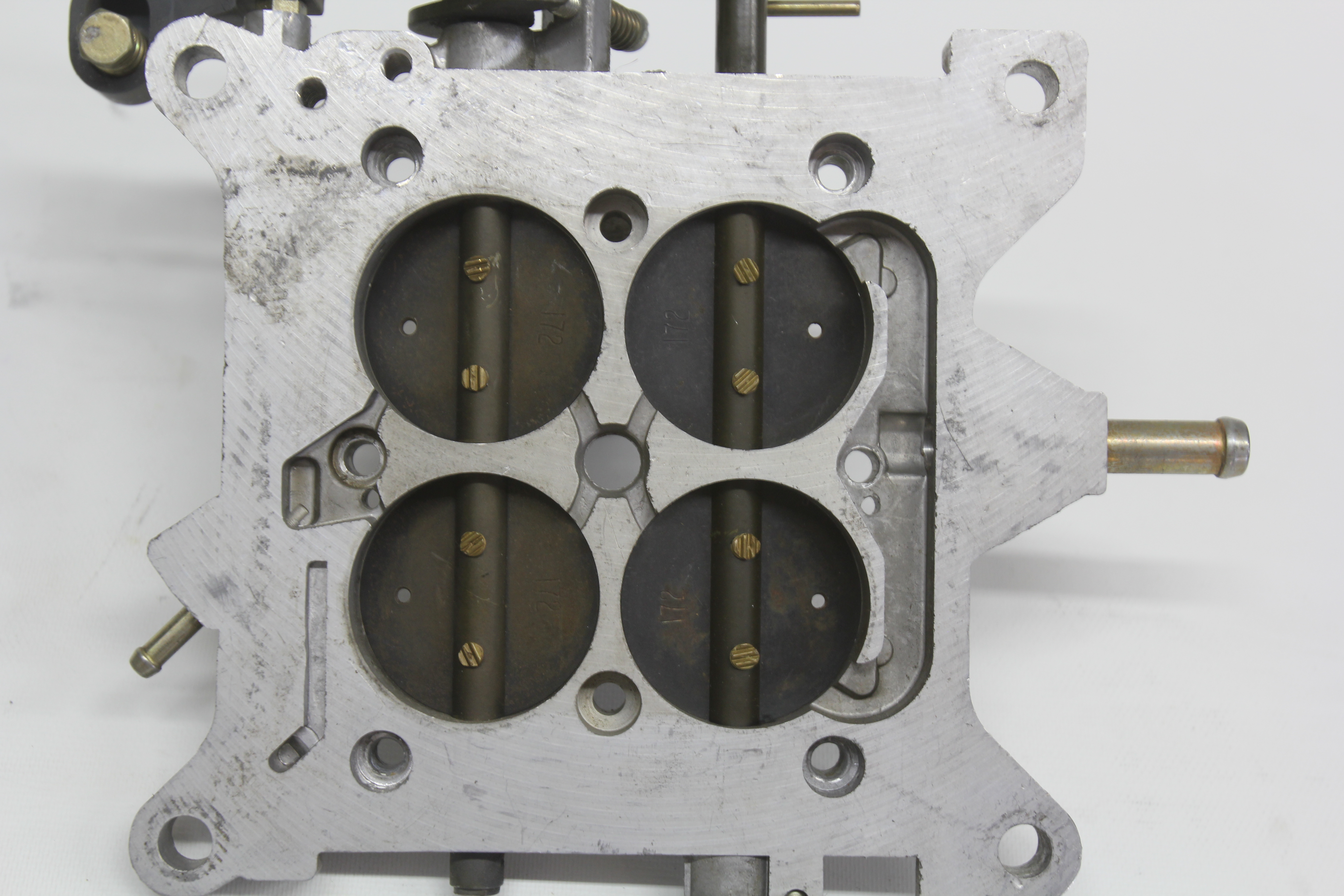
Another major factor in improving big-cam drivability is the placement of the throttle blades. As discussed, with reduced manifold vacuum, the engine does not have enough vacuum (which is the pressure differential) to pull air past the throttle blades. The easy solution is to crank on the idle speed screw to attain the desired idle speed. The problem is this uncovers a larger portion of the idle transfer slot. This is a slot located on the opening side of the primary throttle blades and as the throttle opens, this exposes more of the transfer slot to engine vacuum, pulling additional fuel out of the idle circuit. With the primary throttle blades now open too far, this exposes the transfer slot to manifold vacuum, which pulls more fuel in at idle – fuel that is not controlled by the idle mixture screw. Plus, because the transfer slot fuel is now flowing fuel at idle, when the throttle is opened more under light acceleration, the engine experiences a significant hesitation.
One time-honored solution to this transfer slot problem is to drill small holes in the primary throttle blades near the transfer slot. These small holes (generally start with a 1/16-inch) will act as an idle bypass and allow you to close the primary throttle blades with the speed screw and return the blades to the proper position relative to the transfer slot. If you really don’t want to do that, you can also try slightly opening the secondary throttle blades to allow more air past. An elegant yet expensive solution is to purchase a Holley HP Ultra carburetor that now employs what Holley calls idle bypass air. This is an adjustable passage (a large, tapered screw) that allows fine-tuning of the idle speed while retaining the proper throttle blade orientation to the transfer slot. All carburetors should have this feature.
To reduce the area of the idle feed restrictor, find a short length of electrical wire and measure the diameter of a single strand. Heavier gauge wire will use larger strands and vice versa. Using a ¼ to ½ inch length of wire, bend it in an L-shape and place the longer end into the restrictor at the bottom of the idle feed restrictor. Make sure the wire feeds through the restrictor hole. With both wire restrictors in place, cover with the metering block gasket and replace it on the carburetor.
Leaning out the idle mixture screws might create a slight sag or hesitation under light acceleration. There should be no clearance between the accelerator pump lever and arm. The accelerator pump arm should begin squirting fuel the exact moment the throttle is opened.
Other Carb Adjustments
Once we have the idle mixture properly leaned out and the throttle blades set correctly, you may experience a slight hesitation on light or heavy acceleration. This can be caused by different conditions. A very common issue is improper adjustment of the accelerator pump arm. A simple check is to lightly move the throttle linkage and see if the accelerator pump arm moves instantly. If it does not, there is probably clearance between the accelerator pump linkage and the arm that actuates the accelerator pump diaphragm.

Photo A
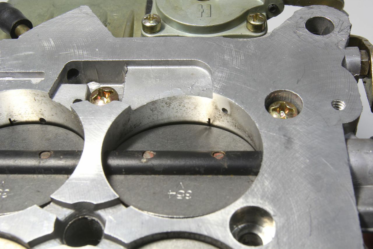
Photo A shows the proper position while photo B reveals the throttle opened too far at idle – which is a common situation for a long-duration camshaft application. When the throttle blades are open too far like this at idle, this pulls more fuel from the transition slot, creating excessively rich mixtures and poor drivability.
If the engine hesitates only when the throttle is moved aggressively from a dead stop, this is a combination of accelerator pump nozzle size and pump cam adjustment. With any hesitation under acceleration, you first must determine if this is due to the engine running too lean or too rich. Carbureted engines will experience a hesitation or sag with either condition and they are sometimes difficult to differentiate. Using an air-fuel ratio meter will quickly point you in the right direction, but this tuning can be done without spending that money if you apply some simple tuning techniques. Add a larger accelerator pump squirter and re-test. If the engine hesitates worse, then the engine is telling you that it needs less fuel – not more. The ideal accelerator pump shot is with the least amount of fuel that allows the engine to accelerate cleanly under all conditions.
Also remember that the accelerator pump cam can be used to change both the amount and the shape of the fuel delivery curve. There are also two mounting holes on a typical Holley carburetor to locate the pump cams. Relocating the pump cam to the Number 2 positon increases the cam lift by roughly 0.010-inch.
Conclusion
These are just a few of the carburetor and ignition changes you can make to improve throttle response and drivability with a long-duration camshaft. The key is to make minor changes one at a time and then evaluate these changes with a test drive before moving on to the next change. This way, you will be able to evaluate each change on its own merits. Making several changes at once tends to mask the results of the individual changes as the first change could easily cancel out the results of the second.
If there is enough interest in a second installment to this story, we can go into more detail on further changes. Once you understand why we are making these changes, you can begin to make your own tuning adjustments based on your greater knowledge of how both the induction and ignition systems work in harmony in regard to engine performance. Stay tuned!
Source
ACCEL Performance Group
accelnation.com
Fuel Air Spark Technology (FAST)
fuelairspark.com
Holley Performance Products
holley.com
Innovate Motorsports
innovatemotorsports.com
MSD
msdignition.com
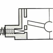
This illustration shows the proper relationship of the throttle blade to the idle transition slot. Just upstream from the transfer slot is the idle feed restrictor. Notice how the idle mixture screw adjusts the fuel after the transfer slot. If the throttle blade is opened far enough to expose fuel from the transfer slot, this nullifies the idle mixture screw adjustment. This illustrates the critical importance of placing the throttle blades in relationship to the transfer slot.
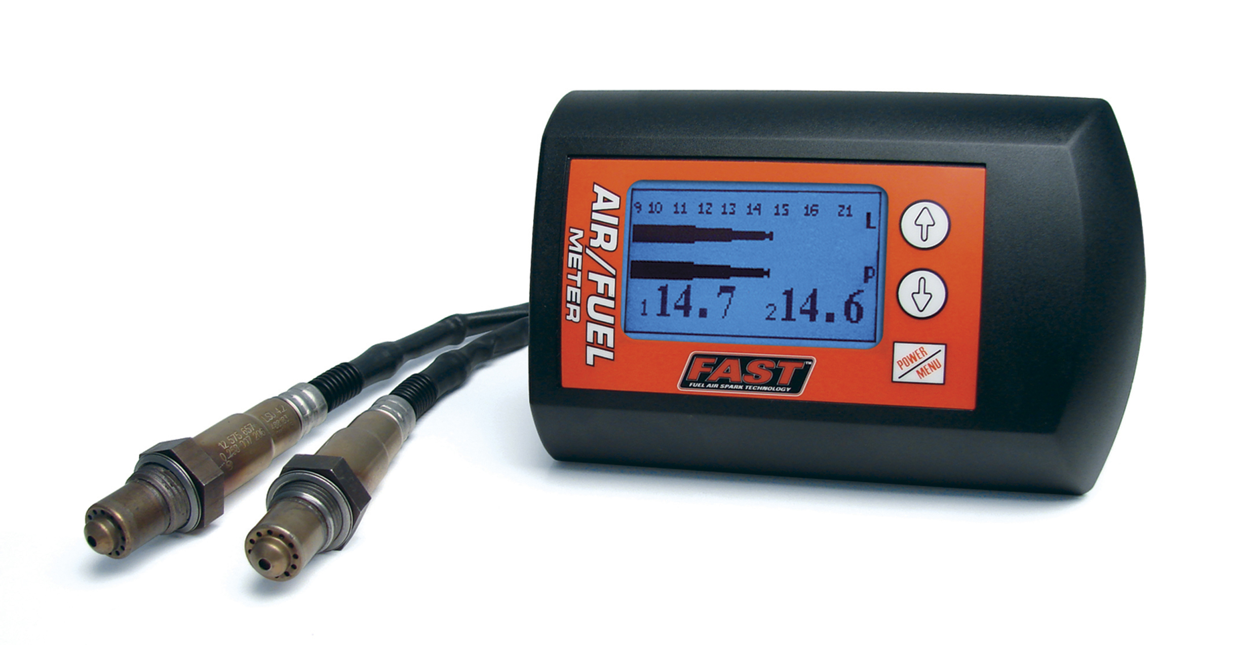
The most useful tool created in the last 20 years has to be the aftermarket wide-band oxygen sensor air-fuel ratio tool. These units deliver a near-instant response to tuning changes that can really save you some time. FAST, Holley, Innovate and many others sell quality units that can make your tuning job really easy.
If holes need to be drilled in the throttle plates, drill on the leading edge of the primary throttle plates and the trailing edge of the secondary plates. Start small (1/16-inch) and drill the holes only large enough to place the throttle plates back in their original position relative to the transfer slot.
Drilling holes in the primary throttle blades used to be the best solution for large camshaft street engine. Holley recently introduced an idle air bypass feature on its new line of HP Ultra carburetors that eliminates the need for drilling. An adjustable channel located under the air cleaner stud will alter idle rpm so that you never touch the idle airspeed screw.

After every significant adjustment, take the car out for a test drive to verify the change. If you make more than one change at a time, you may not be able to determine if perhaps one change negated the other.